
|
| BENVINGUTS - WELCOME | CIENCIA - SCIENCE | IMATGES ASTRONÒMIQUES - ASTRONOMICAL PICTURES | L'OBSERVATORI - MY OBSERVATORY | EINES - TOOLS |
| Com construir un detector RPC How to make a RPC detector | ||||
| | ||||
| | Un detector RPC és un detector gasós basat en dues plaques paral·leles sotmeses a una diferencia de tensió molt elevada que creen un camp elèctric intens. Quan una partícula travessa l'espai entre les dues plaques genera un allau d'electrons que pot ser detectat. Els següents enllaços mostre informació sobre aquest tipus de detector, però es pot trobar més articles a internet. Aquí descric el que fins ara he estat intentant fer d'una manera artesanal, amb el smitjans que es poden disposar sense tenirun laboratori equipat fer aquestes tasques. Es treballa amb voltatges alts així que s'ha de prestar atenció a la manipulació dels elements quan estan en marxa. An RPC detector is gaseous detector based on two parallel plates connected to a High Voltage which create an intense electrical field. When a particle crosses the space between the two plates generates an avalanche of electrons that can be detected. The next links contain information about these detectors, but it is possible to find more information in papers searching in internet. Here there is a description of my research about how to make in a DIY style, without a laboratory specialized in this area. The detector uses high voltages therefore it is important to put attention in the operation of the components. | ||||
 | 1. Elements of the RPC detector A Resistive Plate Chamber detector contains the next elements:
| ||||
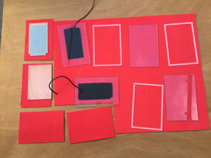
 | 2.
The electrodes One important difficulty of the electrodes preparation is the application of the resistive material on the surfaces of the electrodes. As electrodes I tried with glasses from photo frames, that are very cheap, thin (in the order of 2 mm) and easy to find in diverse standard measures. In my prototype I selected a 18x13 cm glass frame. As a resistive material I elaborated a solution of graphite powder in an acrylic medium. In this case it is necessary to do experiments to obtain the necessary resistivity, mixing different proportions of graphite in the acrylic medium, painting on a surface and measuring the resistivity. When the adequate resistivity is achieved it can be painted on the surface of the glass. No problems appear with this operation because the medium fixes very goon on the glass. After drying it is necessary to verify the resistivity. It it is below the margin with a cutter it can be reduced the thickness of the painting carefully until obtaining the resistivity. If it is above another coat of paint can be applied, but this is not the usual situation. | ||||
 | 3.
The isolators The two electrodes has to be separated with an isolating material to create the necessary gap (in this project 2-3 mm). I used PET plastic because with my 3D printer I can design and build the isolators with the desired distance between electrodes. I tried with 2 or 3 mm. It is important to put each electrode with the glass part in front of the other. The glass parts are face to face, not the conductive surfaces of the electrodes. | ||||
 | 4.
The detection of the signal Over the conductive electrodes I put a piece of EVA foam to isolate the electrodes and placing one conductive plate on each one of it. These plates, for example a printed circuit plate, will detect the change in the electrical field when a particle crosses the detector and generates a flux of charged ions and therefore will alter the electrical field between the electrodes. | ||||
 | 5.
The HV power supply This is one of the most complicated parts of the system. A electrical field in the order of 4-5 kV/mm is necessary and therefore the power supply needs to generate 10-15 kV in our example (2-3 mm gap). The cheapest solution is to employ a HV module easy to buy in internet with a very low cost that can generate electrical fields of tens or hundreds of kV. The problem is that the voltage and current in the secondary has a high ripple due to the process of obtaining the High Voltage. I tried use one of them but after I needed to filter a lot, with HV capacitors and resistances that are more expensive than the module. The result contains ripple. The best option is to employ a commercial module designed to obtain these kV with a very low ripple but it is very expensive. The detectors of the signal in the RPC can detect an oscillation of the electrical field, from the particles or from the noise in the power supply. Now I am trying to design a HV supply based on the well known multiplier circuit with diodes and capacitors, starting with a relative high voltage obtained from a transformer and a pure sine wave oscillator. | ||||
 | 6.
The flux of gas Usually the RPC detectors use a combination of gases, one easily ionizable and other to attenuate the result of the ionization. One of the cases in a lot of cases is Argon and the other is a mix of different gases. At the moment I used the atmospheric air and the results are not specially good. The nitrogen is an ionizable gas but the oxygen cuts very fast the ionization. For this reason my next step is to inject Ar gas mixed with CO2. This combination is easy to find in the bottles dedicated to the arc welding. Although the usual RPCs use this gas as a continuous flux, I will try to do an static contention inside a box with the detector, to obtain a less complicated system and to save money with the continuous use of gas. | ||||
 | 7.
Visualization of the detected signal A good solution to investigate is the use of a oscilloscope, because then we can observe the amplitude of signals and the duration in the time. As the duration of the event is in the order of 25-100 ns, it is necessary to use an oscilloscope with a good bandwidth. The amplitude is in the range of milivolts, this is the reason to have a noiseless HV power supply. With the system characterized and running an amplifier with a level discriminator is possible to obtain the count of the muons detected. The picture shows a possible detection of a muon. The detection and visualization system has to work very fast because the phenomena lasts in the order of nanoseconds. For experiments a fast oscilloscope (in the order of 100 MHz of bandwidth or more) with transitory capture features is very useful. | ||||
 | 8.
Ensambling the components Ensambling the components is easy. In my case I use an extra support made up with the 3D printer in PET plastic and some screws to fix them like a sandwich. As it is an experimental setup it is better to have a flexible system to mount and dismount to experiment with it. Using glue forces to employ more effort to dismount with the risk of breaking the most delicate parts. I does not recommend the use of glue. The red and black cables are the connection to the HV supply and the gray and white the output of signal detectors. | ||||
 | 9.
Operation The HV supply needs to be connected to another power supply of 12 V. The output is filtered with some capacitors to reduce the ripple and a resistive divisor allows measuring the voltage output. In my case I use a value of division of 1000 and therefore the multimeter shows that the voltage in the RPC electrodes is 16 kV (16 V in the multimeter). The resistive divider can also discharge the high voltage capacitors when the power supply is switched off. If you don't use a resistive path to discharge them, then you need to discharge with some metallic but isolated piece. ATTENTION: THE COMPONENTS EMPLOYED HAVE TO SUPPORT HIGH VOLTAGES!!! The usual resistors and capacitors found in the electronic shops will be destroyed and therefore it is necessary components with high voltage specifications!!!! For example companies as Vishay and Murata has High Voltage resistors and High Voltage capacitors respectively. And in ebay it is possible sometimes to find these components too. In this assembly no Ar CO2 gas are used. I am working to add a box to put inside the RPC in a ArCO2 atmosphere. I will explain the results when I carry out new experiments... | ||||
| Information Updated on 2020, January. | |||||